Arici T3
The Arici T3 is a logarithmic calculator which constrains the equations for calculating the dimensions and reinforcements of reinforced concrete for a certain safety factor.

The equations cited in the patent are the following:

Herein,
By converting the equations to logarithms, the order of the operations is lowered, from powers to multiplications, and from multiplications and divisions to additions and subtractions. E.g. equation 1 can be converted to logM + 2logr - 2logd = logb
So it is clear that by gearing certain scales to each other (e.g. log(M) is geared 1:2 to log(r)), for a certain set of starting conditions), all the possible solutions to the equation can simply be read off the scales.
The patent (for the Arici55, debuted in 1955) shows a tantalizing glimpse of how this gearing works in practice:


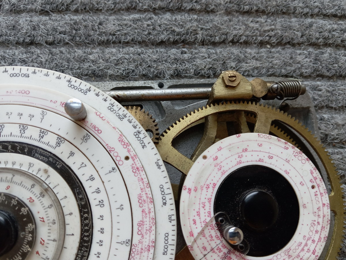
But we can probably all agree that opening up the machine and reveling at the many combinations of gears in various ratios is much more satisfying:


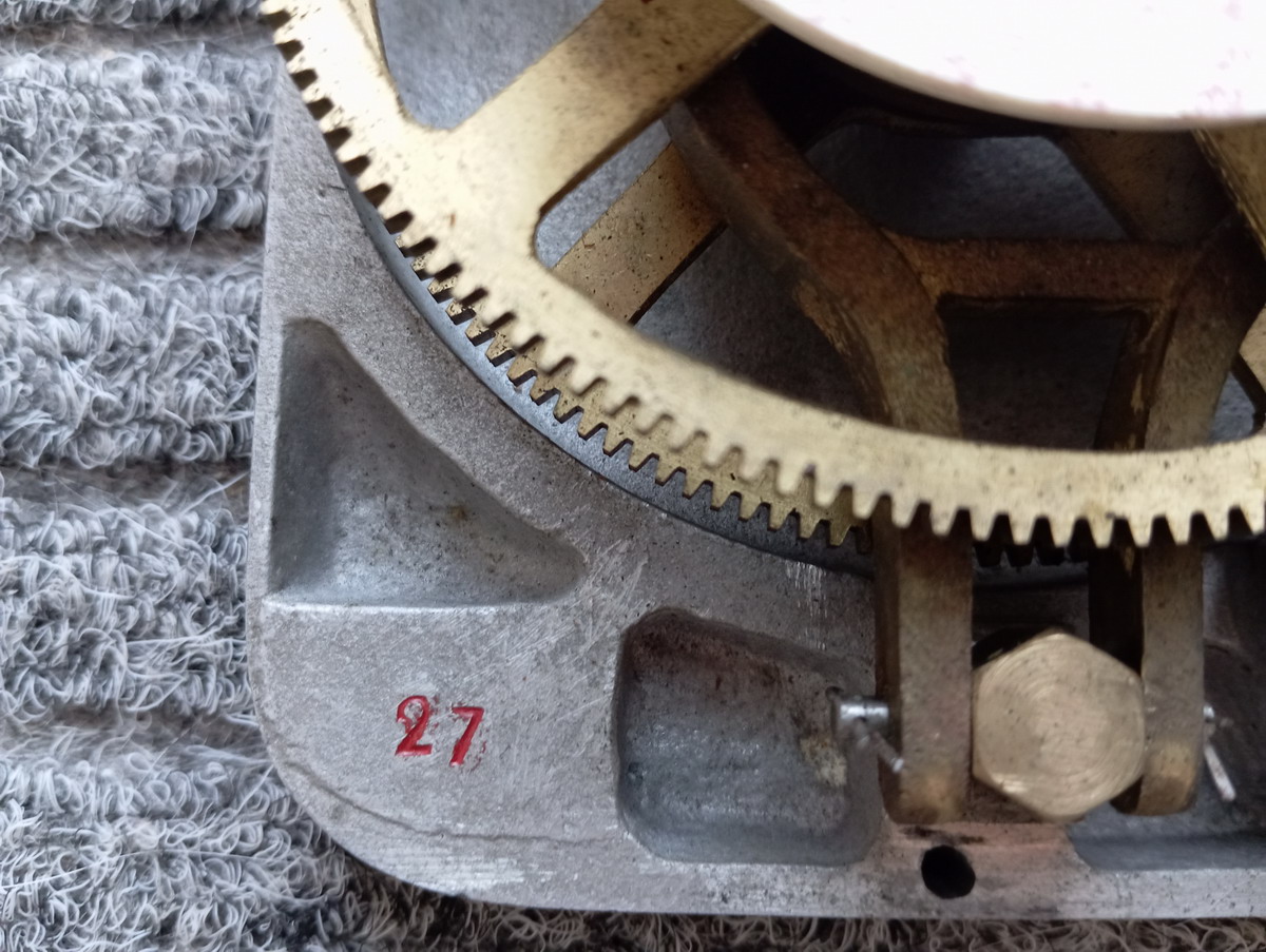
The serial number of this particular machine is probably 27, as this number is stamped into the top of the base, as well as the declutching lever

The lever on the left side uncouples clutches between the middle and outer dials by means of a cam, so that the knobs on the outer dials only move the pointer, and a single scale or set of scales on the inner dial.




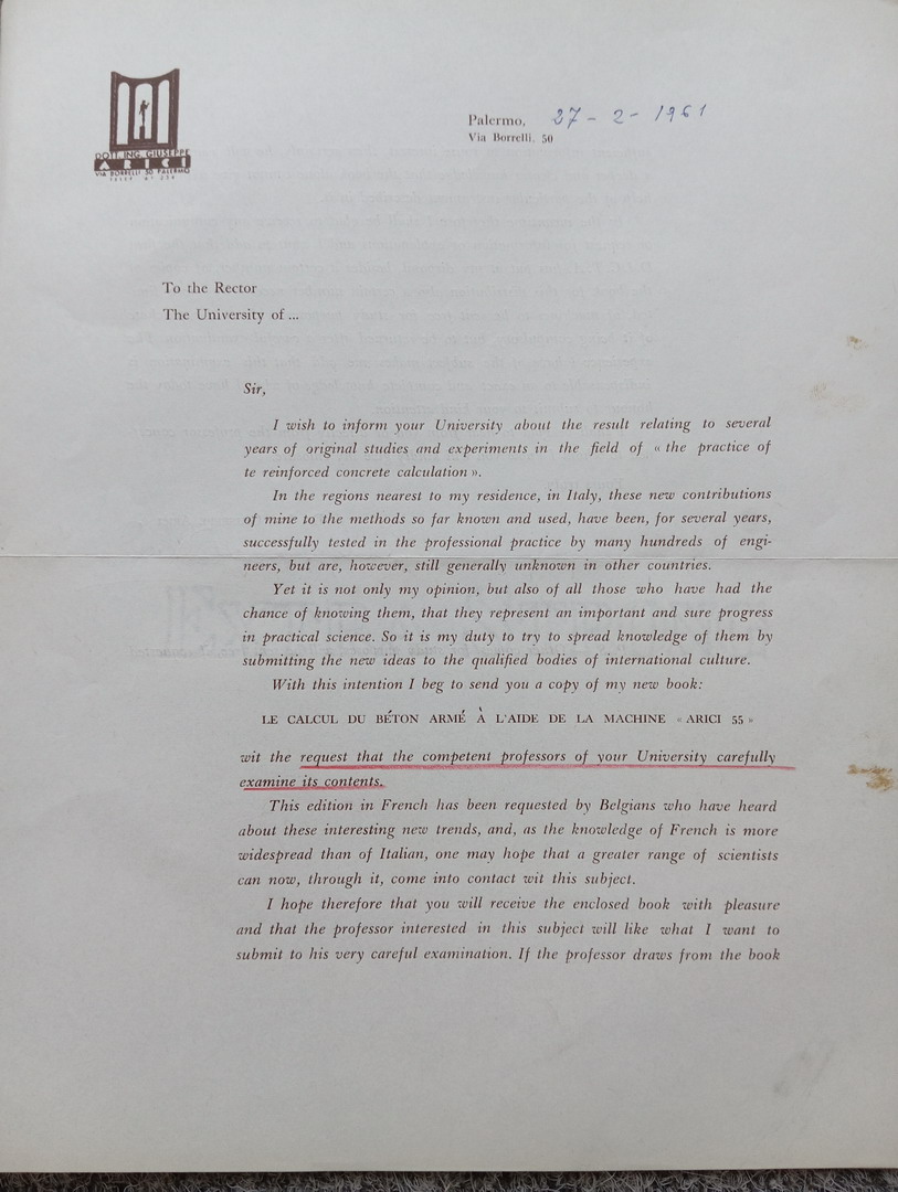
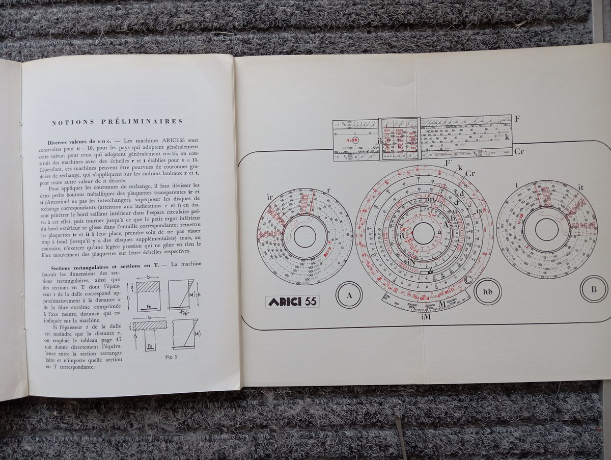
I managed to buy a manual, sent by Mr. Arici himself to the periodical “Cement” - which still exists, by the way ... This manual, in French, was published at the request of the Belgian construction community, because thye were early adopters of the Arici T3.



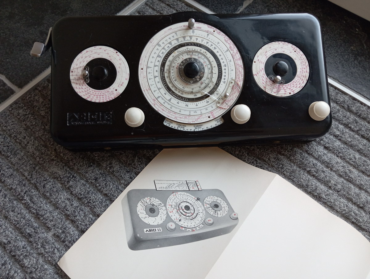
Now some pictures of the assembled machine:


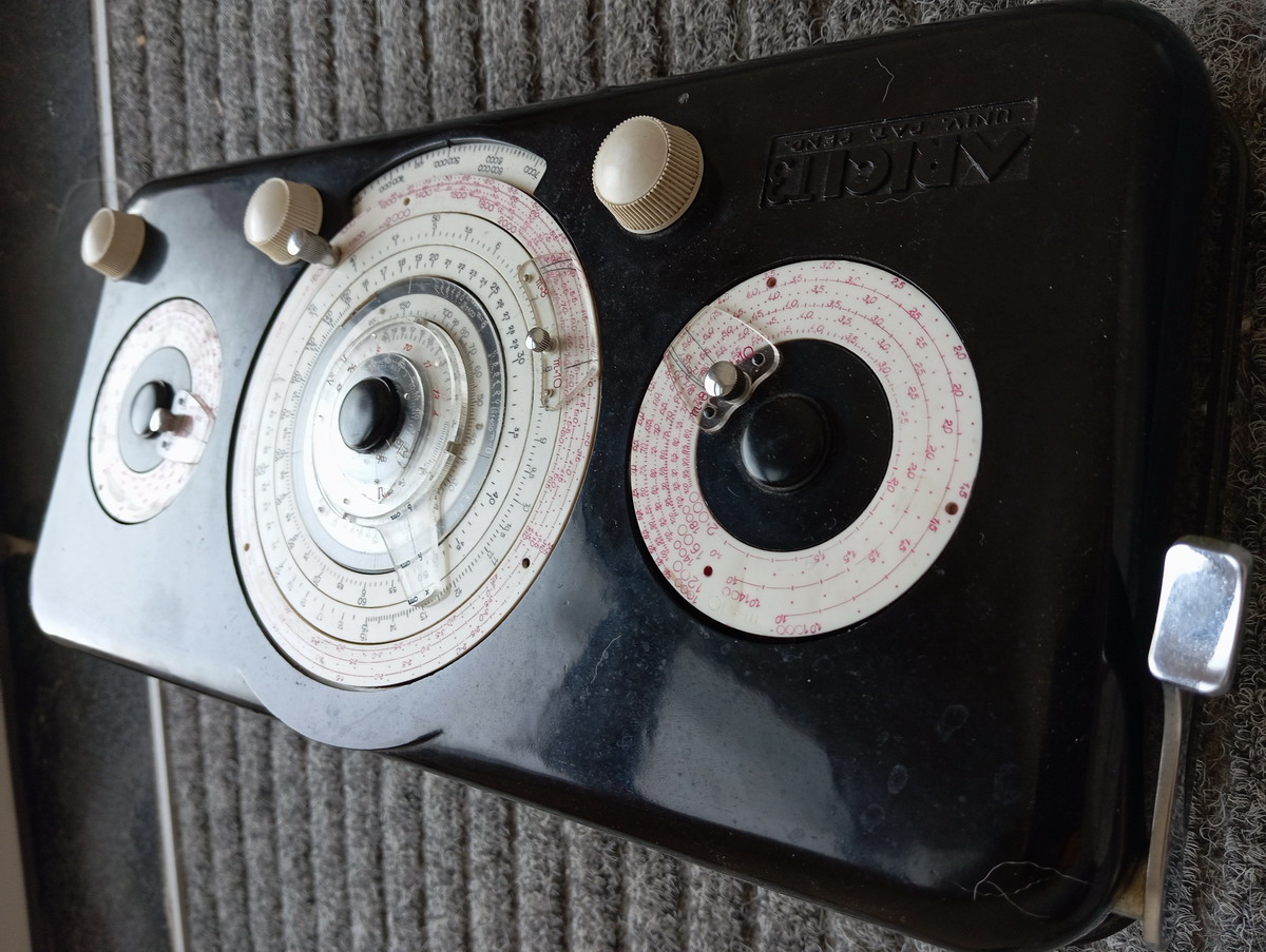


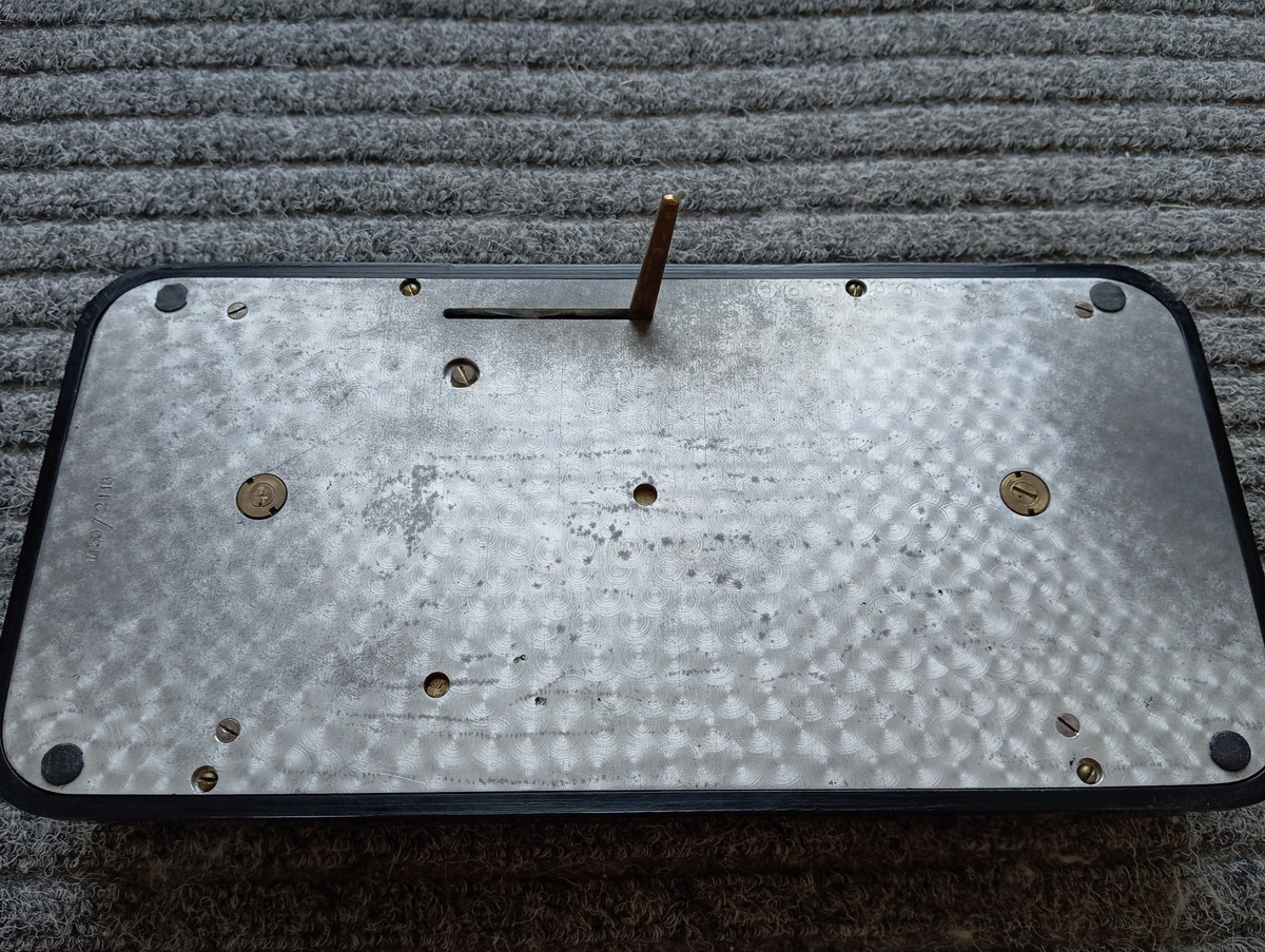

So let’s give it a try with some of the examples in the manual, to give you a feel for how to deal with the machine. The simplest calculation possible is choosing the height of the beam. This is done by pointing the line iP to the scale d.

In this case, we pointed the line on the pointer to h=45cm
In the Arici T3, the pointer is aligned by the middle button, but contrary to the later models (Arici 55), the scale does not follow automatically the rest of the movement of the machine, so if the middle dial rotates by turning one of the outer knobs, the middle knob also needs to be turned to restore the pointer to its place.
The next choice to make (and this is really the setup of the whole machine) is the base tensions fc for concrete, and fs for steel. These need to be set on both of the outer dials. There are six scales on these outer dials, each labeled with the respective traction forces of the steel fs. (1000-2000 in increments of 200). By uncoupling the rest of the machine by pressing the button on the side, the pointer can be set for the respective fs scale, to the desired fc (compression stress of the concrete, in kg/cm²). Again, both of the wheels need to be set to the same combination of fs and fc. The left outer wheel rotates the three outer scales on the middle dial, so x, h and the scale for fc/fs on the middle dial. The right outer wheel to which the same Fs/fc needs to be set, just rotates the scale for the number of reinforcements. Here we set the line for m=10 on the pointer to 45 (fc) on the scale for fs=1600

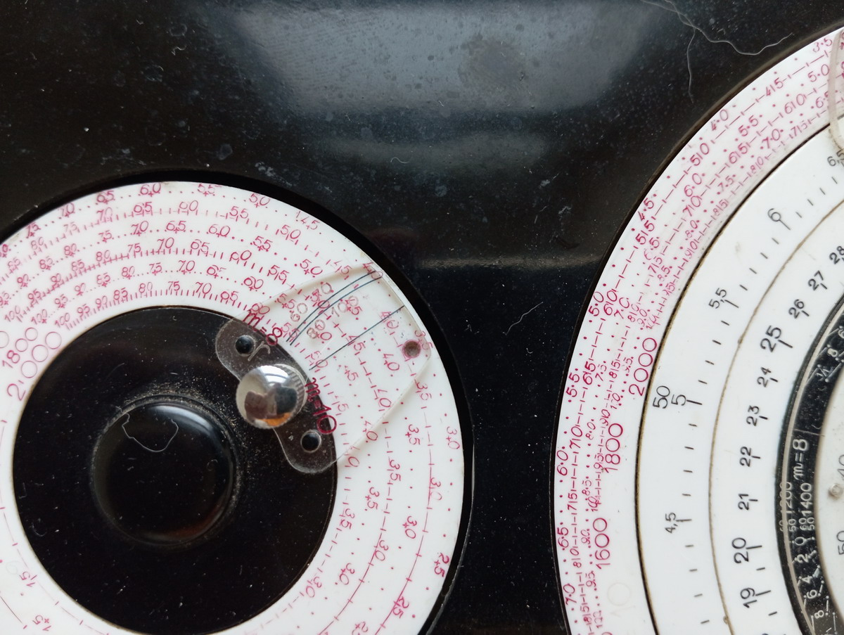
We do the exact same for the right dial

If the distance from the top of the beam to the neutral axis is desired (x), also the pointer “is” needs to be set on the same value of fs and fc on the outer red scale s. This is done by twisting the round chrome knob on the scale s, which just rotates the x scale, and as you can see, the line for m=10 is now set to the fc=45 on the fs=1600 scale.

The next trick is the round transparent disc on the circular base from which the pointer “ip” extends. This contains markings (in red) “ø” and “m/m”. This transparent disc can also be rotated, so that the diameter of the armoring steel (in red numbers on the transparent disc below) is interposed between those two symbols - so here e.g. 10 mm steel.
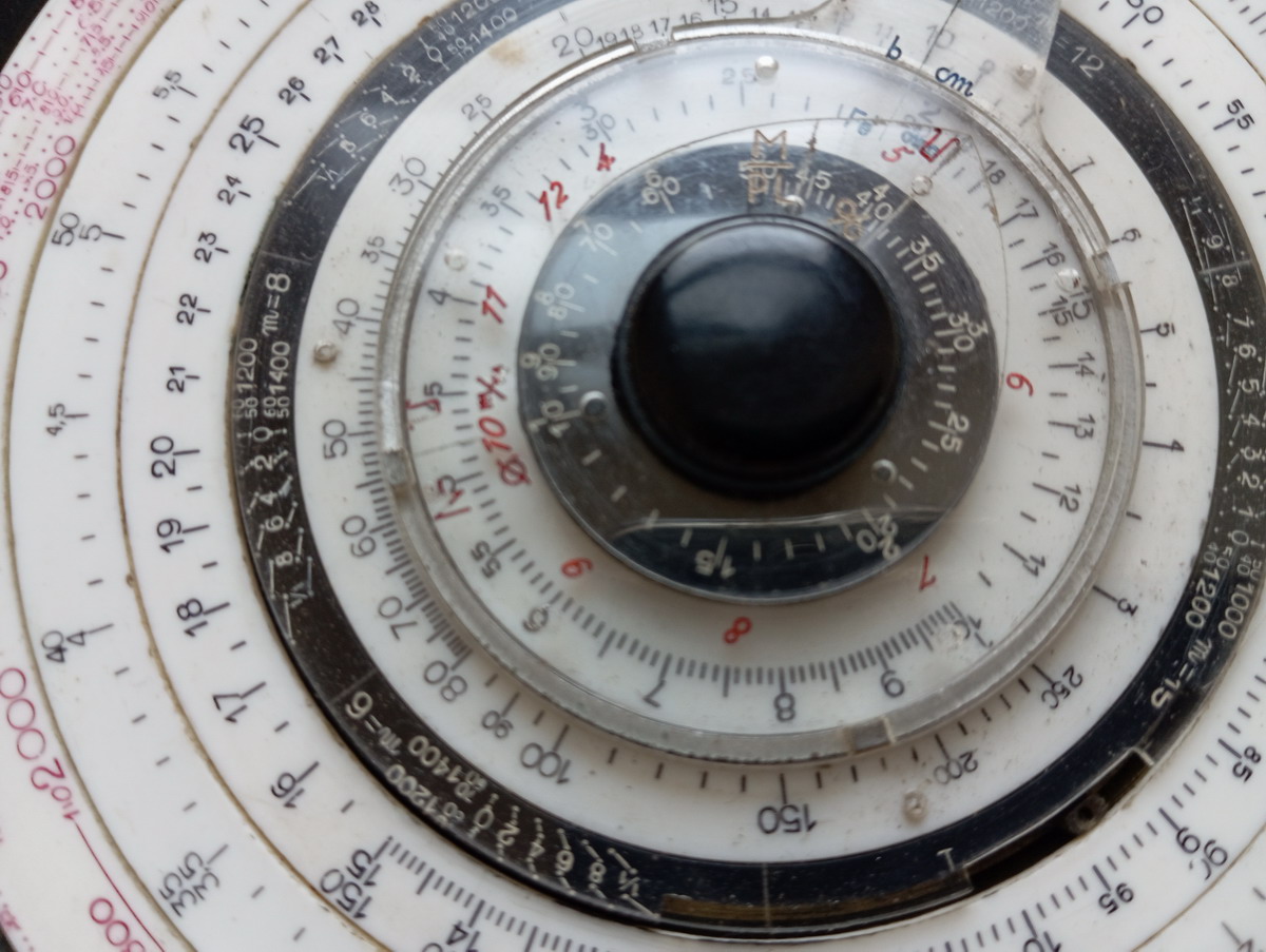
It needs to be rotated to 8mm


Then the pointer needs to be restored to h=45cm

The very outer scale on the middle dial, only visible through a window at the bottom, is the logarithmic scale for M, the bending moment of the beam. This is scaled either in centimeter-kilograms (between 60.000 and 5.000.000) or in meter.kg (between 600 and 50.000). The patent stipulates there would be versions for the “English metric system” - by which they mean measurements in foot-kips and inches (whatever a footkip used to be ?). Everyone by now has probably long forgotten what what a footkip is, and this instrument is metric (well, cgks, in 1950...) anyway. Scale M is rotated either with the lefthand or the righthand button. It is here set to 500.000 cm.kg
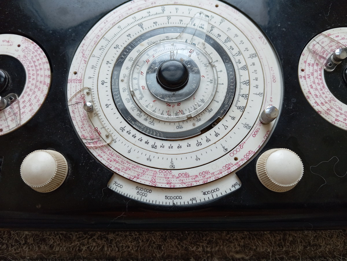
Now, having set up the instrument like this, it is simply a question of rotating the pointer “ip” to a value for one of the quantities desired, and reading off the rest. Say the desired bending moment should be 500.000 cm.kg, then the outer scale is rotated to this number with either the left or the right knob. Then the pointer ip is rotated to a desired quantity - eg imagine the beam height is wanted to be 45cm. Then we know the neutral axis is going to be at x=10.0, the width (b in cm on the scale inside the black circle) needs to be 34cm, and we will need 27 8mm steel bars in the beam, for 7.2 cm² of Fe. (I know this doesn’t sum up, but it must be some weird consideration regarding reinforcement bars and their cross sectional surface, because in the manual, it also never corresponds)


The strengths of having this kind of analog computer where the equatiosn are hard-coded into the mutual rotation of the dials is that you have an entire set of solutions at your fingertips - any variable can be fixed, and any other continuously varied, immediately seeing the effect on all the others - say, if you want to see what increasing the height of the beam to 45 cm does to the width and reinforcements - you just rotate the pointer. If you think 34cm is too wide for this beam, you may change the compression strength of the concrete on the outer dials to 60 instead of 45, and observe the effect - the beam can now be 21.5cm wide, with 23 reinforcement bars.

Or you can change the bending stress, etc etc ...
The calculator can of course be used to the full effect of all four equations contained in it - also e.g. for T-beams, for changeovers from T to rectangular beams, for curved beams, for steel in compression ... the possibilities are endless, as Guiseppe Arici very much liked to propagate.
My main takeaway from the machine is how incredibly satisfying it is to work with - i tis heavy, due to the chunky machined aluminum baseplate and the large brass gears. Operation is very smooth, and the very inertia-rich feeling of these smooth spinning scales along very ordered positive or negative ratios is just so incredibly satisfying .... Allow me to demonstrate in a video, so you can also see the machine in action:
